Atlantic Coast S Gaugers - ACSG
"Promoting S Gauge along the East Coast"
Tidewater Links ▼

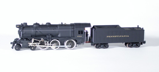
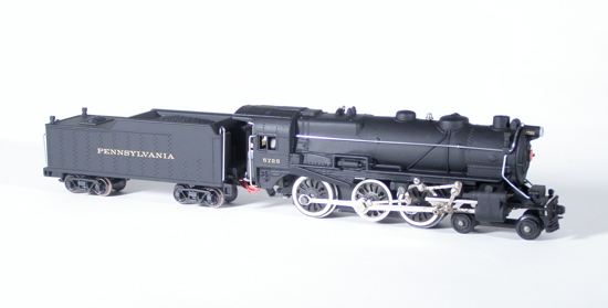
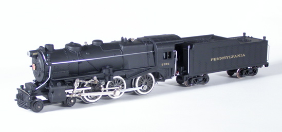
Pennsylvania 4-6-0 G-5

These three pictures show both sides of the finished locomotive. The bell was moved from the boiler front to the top of the boiler. The whistle was moved from the side of the steam dome to the top of the firebox. The cast-on sand piping was removed and applied wire pipes were installed. One of the steps on the pilot had been broken off so a new one was fabricated and installed. I also made a rod and lever to simulate the power reverse mechanism connecting the power reverse unit to the valve gear near the eccentric rod.

The K-5 type drive rods and eccentric rods had to be shortened to fit this locomotive. The tender is a Gilbert Atlantic-type tender that resembles the type used on many of the Pennsylvania G-5 locomotives. I used S-Helper Service tender trucks for this locomotive.

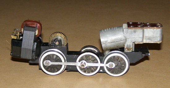
These views also show how the motor protrudes from the cab. One-quarter inch was removed from the plastic rear section to shorten it. Otherwise the tender could not have been attached this closely to the locomotive.


A picture of the two Atlantic-type frames that I modified to be joined together to form a single six-wheel frame with drivers unevenly spaced. The tongue of the unit on the left will fit into the slot of the right unit. They will then be locked together by the three screws. I also used JB Weld to fill gaps and ensure the joint was solid.

This picture shows the frame fully assembled with the drivers mounted. The side rods had to be modified by shortening the forward section and lengthening the rear section. The motor also had to be modified so that it would not protrude from the rear of the locomotive cab too far. I filed the rear of the motor down by about a quarter inch.

The boiler had to be cut up in a similar manner as the Pennsylvania 4-4-2 E-6 I made. The casting was cut just forward of the sand dome and a short section removed. Another cut was made in the middle of the firebox with another section removed. Both of these cuts had to be filed down to form a lap joint so the pieces could be firmly joined together.

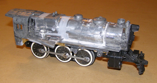
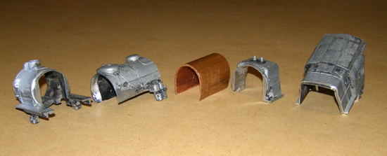
A third cut had to be made behind the steam dome so that section of the boiler could be lengthened. A short section of copper pipe was cut and formed into an inverted "U" shape to fit inside the boiler to bridge the gap.


This picture shows the underside of the assembled boiler. The copper pipe can be seen with the JB Weld fixing it into place.

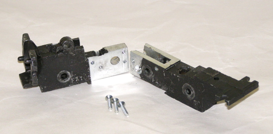
This picture also shows the brass sheeting I formed to attach the locomotive frame to the boiler. The front has a brass sheet attached to the original mounting holes. The Atlantic frame does not fit the same as the Pacific frame; the attaching points are narrower and farther forward so the mounting under the boiler had to be shifted forward. This brass sheet performs that function.

The rear of the frame rests on the brass strip I made to span the rear of the boiler.


The fully assembled boiler being trial fitted to the frame. The boiler details had to be greatly modified for this locomotive. The feedwater heater was removed. The feedwater pump on the left side was removed along with the piping associated with it. The power reverse on the right side was removed and reinstalled slightly farther back near the fire box. The firebox sections below the running boards were also removed, cut down and reinstalled.

The Pennsylvania G-5 4-6-0 pulls a train on Jeff Hill's S Gauge layout on September 9, 2013. (2:49)

Return to ACSG Home