
|
Atlantic Coast S Gaugers - ACSG
"Promoting S Gauge along the East Coast" |
|

|
Atlantic Coast S Gaugers - ACSG
"Promoting S Gauge along the East Coast" |

|
ACSG Modular Layout Specifications (print version of all sections - pdf)
| Basic module wiring: | |
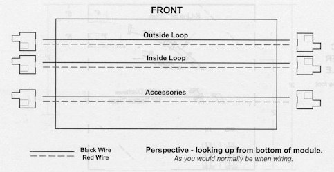
| 2 pin and/or 6 pin connectors | |
| If both are supplied, connections to mating modules with either is possible | |
| The projecting part of the connector in the drawing is the exposed silver pin of the connector. | |
| Track and accessory power lines are no smaller than 16 gauge wire | |
| Black wire to the rail closest to the spectator side of the module | |
| Red wire to the rail on the inside of the module | |
| Feeder wires to track from power lines no smaller than 18 gauge | |
| All connections should be soldered. | |
| Other connection methods that have an equivalent degree of reliability and current transfer capacity would be crimp fasteners (double crimp is best) or reusable Swenco brand butt splices. | |
| Each wire pair marked: outside loop, inside loop, accessory | |
| The accessory power lines are required even if the accessories on a module are powered from separate power supplies | |
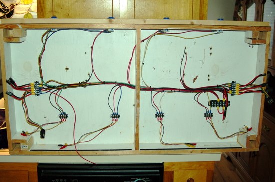
An example showing the buttons along the top, track feed wires, the main bus of wires in the middle, module-to-module connectors on each end, and accessory connectors along the bottom:
Electrical connections:
The diagrams are based upon the use of an AC power source. If using a DC source, modify the circuiting diagrams as required.
BASIC MODULE WIRING TIPS
There are separate wiring busses for the outer loop, inner loop and accessories. Some additional features have been added to the original concept to increase the module's flexibility at shows. These modifications allow members to: arrange and change the accessory layouts on the fly during show set up or operation, remove and replace an accessory that fails during a show, or incorporate accessories into a show layout brought by members who do not own modules. These modifications to the module wiring have lead to some additional modifications being made to operating accessories so that these can be quickly set up on the modules.
An example showing the details of the accessory connectors:
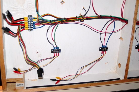
WIRE COLOR CONVENTIONS
Some wiring standardization is starting to be employed by several members in order to simplify module set up at shows. The common color coding of wire helps the members hook up and troubleshoot other member's modules.
| Black: | Common power (AC) or negative pole (DC). |
| White: | This color is used a couple of different ways because it comes in pre-made connector harnesses that we use for module to module and button board connections. The automotive two-pin trailer connectors come with one red wire and one white wire, instead of red and black. Here the white wire carries the "black" common power. On the button boards, where we have been using the Hoppy brand 48035 4-pin connectors, the white wire carries the switched voltage from one of the buttons to one of the accessories. On three-button, button boards, it carries the constant voltage, red wire, to the buttons. |
| Red: | AC "hot" or DC positive. This color is used for power that is going to the inner or outer loops. It is also used for accessory power that is NOT controlled by a switch or button. |
| Yellow: | Switched voltage (AC or DC), used to power accessories and controlled by the operator, the visitors or a sensing device. (Same as red except switched.) |
| Green: | Variable voltage for tracks in controlled blocks on sidings, i.e. CAB controlled track power. |
| Ribbon Wire: | Black/Red/Yellow/Green: Remote control turnout wiring. |
| Green/Yellow/Brown/White: Used to supply power to the accessories from the button boards. The Hoppy brand 4-pin connector, #48035, has these colors. Each wire carries the switched voltage from a button to the accessory it controls. A separate red wire supplies constant power to the buttons from the accessory buss. A black wire from the accessory to the black accessory buss completes the circuit. If you use three buttons per module instead of four buttons, the white wire carries the "hot" voltage to all the buttons. The green, yellow and brown wires carry the switched voltage to the accessories. | |
| If you use 6-pin connectors (Hoppy 47995) to connect your modules to the next module, the following color codes are being used in the Carolina Division: | |
| Green: | Outer loop common. |
| White: | Outer loop "variable." |
| Brown: | Inner loop common. |
| Red: | Inner loop "variable." |
| Yellow: | Accessory common. |
| Blue: | Accessory "hot", unswitched. |
| Red, White and Blue are positive. | |
The Yellow and Blue are AF box colors and since they have not been used for track power they were chosen as the accessory colors.
All the "positive" voltage colors are aligned on "top" of the connector. The Green/White, Brown/Red, Yellow/Blue are next to each other.
The RED pin has the same male/female orientation at the module ends as the old 2 pin connectors.
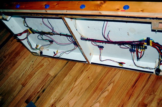
An example showing buttons along the top, track feeds, 2 pin and 6 pin module-to-module connectors, and accessory connections along the bottom:
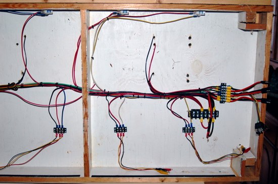
| WIRING MATERIALS TIPS | |
| A. | Radio Shack does not sell 16 gauge stranded wire. The best source for wire is at automotive stores. They sell 14 and 16 gauge "primary wire." Thirty feet of 16-gauge wire is $2.79. One hundred feet is about $5.99. If you build more than one module, the 100-foot roll is a better deal since you need extra wire if you have operating accessories wired to your module. Northern Tools and other automotive supply shops sell unusual colors of wire, white, brown, green blue, etc. Some Advance Auto Stores have $4.99 as the price on the shelf. They will honor that if you get a price check before purchase, otherwise they charge $5.99. Metro Auto Supply in Columbia SC sells it for $4.97. Auto Zone does not sell 100' spools of 16 AWG, only 30'. NAPA sells some wire for 3X the cost of everyone else. Hesco in Columbia sells NICE 12 AWG black and red "Zip Wire" for $0.30 per foot. This may be the ultimate overkill or it may be a really good idea. One chart we have seen lists 14-gauge wire as suitable for carrying 15-volt 3-amp circuits for 30 feet without appreciable loss of current. For a 35'x 35' layout the current must travel a minimum of 70-feet. Twelve gauge may not be a bad idea for the through wire part of each module. Our current modules are wired with a minimum of 16-gauge wire as of 4/03. Hoppy Brand 4-conductor 14 AWG wire, 49905, is available for $10.89 per 25'. Add a Blue and Red 14 AWG wire and you are set for using 6-pin connectors. |
| B. | Radio Shack electrical connector #270-026 is specified in the ACSG module standards and is constructed with only 22-gauge wire. Auto stores sell the same basic connector as a 2-wire trailer connector with 16-gauge wire. 16-gauge wire has 400% less resistance than 22 gauge. 22-gauge wire does cause voltage drop problems on the larger layouts. Most or these automobile supply store connectors are set up with red and white wire as opposed to RS's red/black scheme. When you are doing your wiring just match the red wires up and mate the white and black wires together. This will match what others have done. Some packages claim the wire to be 24" long. Most are really only 12" long. If there is very little wire in the package, expect it to be 12-inches long when you open it. Several auto stores sell the incorrectly marked wire. Auto Zone, Advanced and Pep Boys sell "Hoppy " brand 2-pole flat 12" trailer connectors, #47965, these work, but as noted above the wires are white and red. |
| C. | Don't cut the #270-026 2-pin style connector wire in half. If you cut the 12-inch wire so there is one long end and one end with about 1" of wire, then you can use the long end and connect directly to a RS #274-656 2-position dual row barrier strip. If you do this, you can tap off the 2-position barrier strip to your rails or to the accessory buss, and also tap off for the through wire used to connect to the next module. Piece the short wire 2-pin connector to the far end of this through wire buss. Using the barrier strip makes a neat way to tap off to whatever you are doing locally on your module and it allows for changes on the fly. Soldering connections slows down modifications. Wait, this may be a good thing! See diagrams. |
| D. | When looking at the Specifications wiring diagram, pay attention to male / female. The ACSG Module Standard drawing is a little confusing but has the male / female correct. The silver pin is male but is shorter than the female on the actual connector. Hook up the wiring while the module is upside down so you don't have to work underneath it. The diagram will be correct this way also. Even if you do this wrong and short out the transformer, just disconnect your module wires and allow the adjacent modules track to power your track until next show. Also, see the attached diagrams. |
| E. | "Hoppy" brand 6-pin connectors are $2.39 in Kansas. This is way cheaper than getting 3 of the 2-pin connectors. Currently 21 of the Carolina modules are being converted to 6-pin connectors. Contact Calvin or Ted for wiring information if you plan on converting. The red pin has the same Male / Female orientation as the 2-pin set up. Treat the Red, White and Blue wires on the connector as Red and the other 3 wires on the connector as Black. White is outer loop variable voltage, red is inner loop and blue is accessory loop. Converting the modules to the six-pin connectors eliminates the possibility of connecting the inner and outer loops together and eliminates four connections per module, saving setup time. Currently, if you decide to use the six-pin connectors, you need to also provide a two-pin connector for each buss so we will be able to hook up to modules that have not been converted. This would include all the other divisions of ACSG. An alternative is to make 2-pin to 6-pin adapter harnesses that you can use to connect to a module that still uses 2-pin connectors. Tractor Supply, they have stores in Columbia and elsewhere, sells the 6-pin connectors for $1.99. |
| F. | Lowes is about the best source for ring terminals and crimp type connectors. "GB" brand connectors are $1.05 for 22. Lowes does not carry red #6 stud ring connectors. Lowes only has the blue ones for #6 ring terminals. It is cheaper to buy them in the small packages. Radio Shack has #6 stud red ring connectors. |
| G. | Reusable butt splices available at auto parts stores work very well. Autozone and Advanced sell them as "Posi-Lock" by Swenco. The part number for the 10 piece pack is PL1824-10. The 18-24 Gauge size fits 16-gauge wire also. The connector is even UL listed for 600 VAC. Extreme overkill for toy trains. (We like that in an electrical system.) Tractor Supply Company sells 100 piece packages. They have other items by Swenco also. See Swenco @ www.posi-lock.com |
| H. | Auto Zone and Pep Boys have a "flush mount horn button" made by Conduct Tite, model #85929. It sells for $2.99. Most have a high failure rate. Buy only the ones with shiny chrome, head of terminal screw should be same size as mounting screw. Stamping should have crisp, not rounded corners. It may be safer trying a different button. On the poorly constructed ones, the spring goes flat and the button won't "push" after one or two shows. This generally sucks. AC Delco U1980 horn button for $3 is available at parts stores selling AC Delco. We have not had any failures with these. They are worth the extra effort to special order. Caltherm at Pep Boys is OK ($3.99). ($2.79 in Kansas) Vending machine or video game buttons may be the best choice. They have a large face and the actual switch is a high quality micro switch. The switch has Normally Open and Normally Closed contacts. Skycrafters electronic surplus in Orlando Florida has these for about $3 each. Ted Zanders has them mounted on his button boards and the Tidewater division has also started to use them on their units. They require a recessed hole so the micro switch can fit behind the push button. This requires that the button boards hang below the fascia board or that the buttons be mounted into the fascia board and the skirts must be modified as the Tidewater Division has done. Call Tidewater up if you are interested in this scheme. Since vending machine buttons are lit, they look REALLY GOOD when connected to a flasher. (Automotive flasher won't work since the bulbs don't draw enough current to heat up the flasher.) |
| I. | April 2003 update: Caltherm buttons do not hold up well near the ocean, the "chrome" turns dark and the internal contacts corrode. High use buttons such as whistles need to be replaced before every show. Make wiring long enough to accommodate changing out the buttons from the public side of the module on the fly at shows. Ken Mc Nelly will be trying the Skycraft micro switch buttons. |
| J. | To make accessory busses that are very flexible, use the following: 8-position dual-row barrier strip and an 8-position bus strip RS #274-650. Make a black wire buss and a red wire buss with these to hook up operating accessories. RS jumper leads 278-1157B with one end cut off and replaced with a red #6 stud terminal ring make quick set up accessory connections. See diagrams for additional detail. |
| K. | Add an accessory buss kill switch and mount it on the inside fascia of the module. Radio Shack #275-731 works nice. It is a lighted automotive rocker switch. Drill a 15/16 hole in the 1 x 4 and just push it in. It works fine with 3 to 18 Volts AC or DC. A little red LED comes on when the buss is powered and confirms to the operators, at a distance, that your module's accessory buss is receiving power. The kill switch allows you to shut off power to just your module if something starts to smoke or someone is pushing a whistle button too often. Switches have a failure rate of 1 in 50 per show. Get an extra one. (Credit for the kill switch concept goes to Joe Haenn). |
| L. | Add a circuit breaker or fuse to your accessory buss between the dual row 8-position barrier Strip and the accessory Buss kill switch. This breaker should be less than 10 amps so it trips before the 10-amp automotive blade fuse on the club's transformer blows. Without this protection, if you accidentally spark a wire, it will take out the accessory power to every module on the layout. (C'est le grande bummer!) Make sure to have a through wire for the accessory buss that goes from one end of the module to the other, just like the track power, that doesn't have a switch or breaker. The switch and breaker tap off this wiring and feed your module's local accessory buss. "Philmore" brand breakers are mislabeled. I have purchased 5 amp breakers from 2 different sources in packages that say 15 amps and have a 5-amp label on the breaker. They are 15 amp. GC brand is OK, but hard to find. Philips EGC makes a USA manufactured breaker part number CB2-5A that looks good and works well. NTE makes an identical in appearance breaker Part Number R59-5A; it is made in the Philippines. |
| M. | Radio Shack mall stores will carry fewer electronic components in the coming years. Strip center stores will still have a full selection of electronic parts as of fall 2002. |
| N. | Another accessory buss that has been used successfully is a bare copper wire. If using this it is helpful to make a transition harness with alligator clips which would allow a "standard" button board to be attached to your module. These button boards are typically set up to connect to a barrier strip. |
An example showing the details of the track feed wires and an Elk power supply connector:
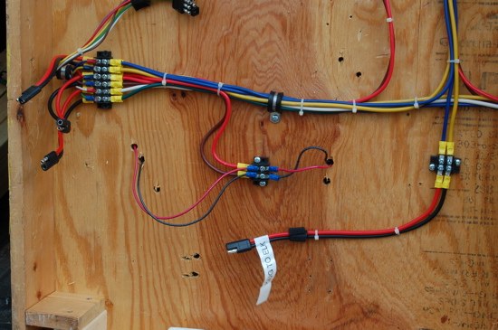
| ELECTRICAL MATERIALS LIST | ||
| A. | The following list of materials is what is typically used in one of Calvin's modules: | |
| 1. | (4) 8 position barrier strips RS 274-670 | |
| 2. | (4) buss strips RS 274-650 | |
| 3. | (4) 3 or 4 position barrier strips RS 910-3193 or 274-658 | |
| 4. | (2) 6 position barrier strips RS 274-659 | |
| 5. | (2) six pin connectors Hoppy 47995 (only 1 if not making a conversion harness to 2 pin) | |
| 6. | (4) 2 pin connector pairs (only 1 if not making a conversion harness) | |
| 7. | (1) RS LED Switch RS 275-731 | |
| 8. | (1) 5 amp breaker | |
| 9. | (1) surge strip with 4' cord Belkin F5C050 or equivalent | |
| 10. | Krylon Spray paint for module edges (dries fast) | |
| 11. | (26) small Adel clamps | |
| 12. | 100 #6 ring crimp connectors | |
| 13. | Gator Grip tape | |
| 14. | Hoppy 49905 14 AWG wire, plus a spool of red and a spool of blue | |
| 15. | Hoppy 48035 4 wire connector | |
| 16. | 14 Swenco butt splices (PL 1824-10 fits 14-16 AWG, but not supposed to) | |
| 17. | RS alligator clip leads 24" RS 278-1157b | |
| 18. | 60 #8 screws ½ " | |
| 19. | White Gloss Kitchen and bath paint (for underside) | |
| Cost is about $89 plus paint | ||
| B. | The following list of materials is what is typically used in one of Calvin's button boards: | |
| 1. | (4) Caltherm horn buttons | |
| 2. | (1) 48" Oak 1x 4 | |
| 3. | (1) 4 pin connector | |
| 4. | Misc wire (scrap from #14 above) | |
| 5. | 8 crimp #6 ring connectors | |
| 6. | 1 "Bullet" crimp connector | |
| 7. | 3 Swenco butt slices | |
| 8. | Tie wraps | |
| 9. | (4) brass Card Holders and #2 screws | |
| Cost about $27.00 | ||
| C. | The following list of materials is what is used in the auto-block control unit: | |
| 1. | Radio Shack Metal Utility Box 270-253A | |
| 2. | "The Detective" | |
| 3. | SKY brand relay SKMP-4C12VDC (4PDT with 12 VDC coil and 5 amp minimum) | |
| 4. | Young ND8Q-14 Socket for above | |
| 5. | RS Full wave Bridge Rectifier 276-1185 50 V 25 Amp for $2.99 | |
| 6. | Tie wraps | |
| 7. | Red Swenco posi-loc butt splices | |
| 8. | Crimp connectors for relay socket | |
| 9. | Skycrafters vending machine switch | |
| 10. | Several 2-pin connectors | |
| 11. | Rubber grommets | |