|
Atlantic Coast S Gaugers - ACSG
"Promoting S Gauge along the East Coast" |
|
|
|
Atlantic Coast S Gaugers - ACSG
"Promoting S Gauge along the East Coast" |
|
ACSG Modular Layout Specifications (print version of all sections - pdf)
| Overall Specification for a Module: | 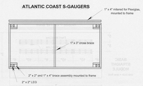 |
|
| Size: | 2' x 4' | |
| Height: | 36 3/8" for Tidewater 37 3/8" for Virginia 41 3/8" for Carolinas |
|
| Legs: | 2" x 2" | |
| Edges: | 4" for 4' sides and 3" for 2' sides | |
| Bill of Materials | ||
| Quantity | Description | Use |
| 4 | 2" x 2" boards - length depends on the division | legs |
| 4 | 3" carriage or elevator bolts and "T" nuts (3/8") | leg height adjusters |
| 3 | 1" x 4" x 48" boards | sides and plexiglas holder |
| 3 | 1" x 3" x 22 1/2" boards | module ends and brace |
| 1 | 2' x 4' x 3/8" plywood sheet | module top |
| 4 | 2" x 2" x 2 1/2" boards | leg supports |
| 4 | 1" x 3" x 3" boards | leg supports |
| 3 | red wire - 16 gauge - 5' long | module wiring |
| 3 | black wire - 16 gauge - 5' long | module wiring |
| 6 | 2 pin connectors | module wiring |
| 2 | 6 pin connectors | module wiring |
| 1 | 2' x 4' green cover (carpet) | module cover |
| 2 | 3" C clamp | module to module clamp |
An example 4' module:
| Framing Method: | 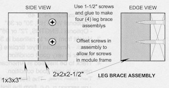 |
|
| Use screws and glue to build frame and secure plywood to the frame. | ||
| Use a good grade carpet adhesive to secure the carpet to the plywood. | ||
| Mount legs so that the module is stable and level with neighboring modules. | ||
| Use screws to mount the plexiglas holder to the frame. | ||
| Secure the holder flush to the top of the module frame after plywood is attached. | ||
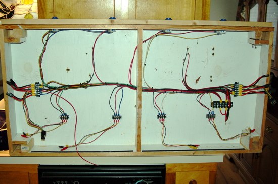
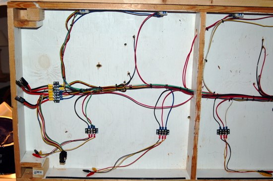
Close up of the framing:
| Track Specifications: | |
| Two parallel lines | |
| Track: American Flyer track or equivalent | |
| 4 straight track pieces per line mounted on module | |
| 2 straight track pieces - not mounted - for connection to next module | |
| 10 straight American Flyer rubber roadbed or equivalent | |
| Front track: 5" from each end of module and 5" from front edge | |
| Rear track: 5" from each end of module and 5" from front track | |
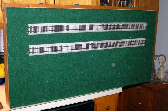
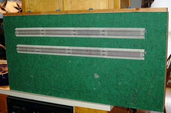
Track side view of 4' module:
| Straight Module Specifications: | 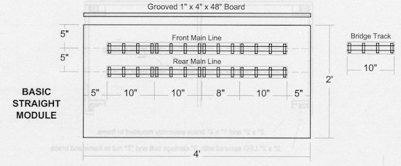 |
|
| Basic module: 24" x 48" Optional widths: 30" and 36" Optional length: 72" |
||
| American Flyer track, or equivalent, in very good condition | ||
| American Flyer rubber roadbed on all sections of track | ||
| Outside track centered 5" from front edge of module | ||
| Inside track centered 5" from outside track | ||
| Tracks end 5" from each end of the module | ||
| Two 10" "bridge" sections of straight track supplied to connect to next module | ||
| Modules are structurally connected to the next using C clamps | ||
| Owner can scenic the module as he/she wishes | ||
| Plexiglas is inserted into a holder screwed onto the front edge of the module | ||
| The holder is mounted flush with the top of the module | ||
| Corner Module Specifications: | 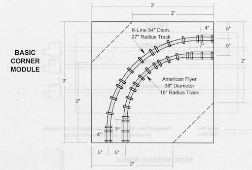 |
|
| Basic module: 36" x 36" Optional sizes: 48" x 48" and 60" x 60" |
||
| American Flyer track, or equivalent, in very good condition | ||
| American Flyer rubber roadbed on all sections of track | ||
| Outside track centered 5" from front edge of module at end to connect with next | ||
| Inside track centered 5" from outside track at end to connect with next module | ||
| Tracks end flush with end of module in 36" x 36" version | ||
| Four 5" "bridge" sections of straight track supplied to connect to next module | ||
| Tracks end 5" from each end of the module in 4' and 5' versions | ||
| Two 10" "bridge" sections of straight track supplied to connect to next module | ||
| Modules are structurally connected to the next using C clamps | ||
| Owner can scenic the module as he/she wishes | ||
| LUMBER | |
| A. | Lowes sells 2x 2 lumber with finger joints. It is called "Top Choice". Since the grain does not always run parallel with the wood, it will not sand smooth. Use it to build a nice fire in the fireplace. Home Depot is not any better. Go to a real lumberyard and get wood with straight grain, very few knots, and no finger joints. The reason they use finger joints is to use up short pieces of wood that would otherwise become pulpwood. Lowes and Home Depot sell nice hardwood 2x 2s for more $$$$. Cutting a 2x 4 down works if you have a table saw. A 2x 2 is actually 1 3/8" x 1 3/8". A 2x 4 is 1 1/2 by 3 1/2". You will need to set the table saw to 1 3/8" and cut the wood twice to make it 1 3/8" x 1 3/8". This will allow you to use either a 2x 2 or the specially cut legs. Be advised, you need a GOOD table saw and GOOD skills to match a preformed 2x 2. Be sure to place the factory cut edges of the 2x 4 against the fence and saw table. Clear the saw dust off after each pass through the saw, if it ain't level it won't be square. |
| B. | 3/8-inch plywood is now called 11/32 plywood at some stores. (Don't travel the entire universe hoping to find 3/8".) A/C is rarely found, B/C is more typical. This will do fine under carpet or other ground covering material. They sell it cut into 2 foot by 4-foot sections, but the grain does not always run lengthwise. You will have to check around. If you buy a whole sheet you can build four 24" x 48" modules and the grain will run lengthwise. This will help minimize warping and sagging of the tabletops. The last cost we paid was $15.70 for a whole sheet. The 2-foot by 4-foot pieces are $4 or $5. Lowes no longer sells 3/8 cut sheets in Columbia as of 10/02. Home Depot still has the 2' by 4 ' pieces so check with your local dealers. |
| LAYOUT | |
| A. | Measuring: Be careful how you mark lumber, track and wire. Which side of a line you cut on can make a 1/16" to 1/8" difference. This can make the difference between a track bridge that fits and one that doesn't. |
| B. | Make sure your module is square and flat. If your plywood grain does not run perpendicular to your module ends, add another 1x 3 cross brace and space the two of them equally in the 4'-0" length of the module. Be wary of building your module on a concrete floor, they are seldom flat. All modules wider than 24" need 2 cross braces. |
| C. | Do not use 1x 4 cross braces or end braces as they will damage track on other modules when yours are stacked on top of them during moves, setup, take down or storage. Using 1x 3s allows a 1-inch space between the cross bracing and the top of the board on the module below. If you have later style turnouts you will need more space than this to clear the signal light housing. Design a spacer to be used with your modules that have turnouts or be careful how they are handled. Even if you can stack them OK, be careful that someone doesn't inadvertently slide a module off of yours and displace or damage the turnout. |
| SOME MEASUREMENTS TO HELP YOU REGARDLESS OF THE TYPE OF TRACK | |
| A. | At the Columbia GATS show in June of 2001, the top of the plywood was 40" to 40 �" from the floor. If you use AF track with rubber roadbed on the Lowes Carpet, adjust your legs for this before you leave home and you should be "show ready". Railhead height should be about 40 11/16" (40.671" if you are picky). In real life, the trains run fine going up and down a �" module to module difference as long as the railheads meet. The bridge track can handle a �" difference and the hi-rail couplers are large enough to stay together. In the future, as we try to better accommodate scale equipment, this differing railhead and table top height between modules becomes more critical mainly because the scale knuckle couplers are much smaller and so cannot slide up and down as far without sliding past one another and coming uncoupled. The most common top of plywood height at Raleigh was 40 �". At the Richmond benefit show in August of 2001 almost all modules had a top of plywood between 36" and 36 �". (Add .671" to get to the railhead: Carpet .1", AF rail .545", rubber road bed .026" equals .671".) In order to get these numbers the adjusters must almost be flush if you cut 35" or 39" legs. |
| B. | Track measurements from bottom of the tie to railhead: | |
| 1. | AF .542" to .545" without roadbed, this includes switches | |
| 2. | K-Line .525" without roadbed | |
| 3. | Pike Master .265" | |
| 4. | Gargraves .450" | |
| 5. | SHS Flex .271" | |
| 6. | American Models Flex .249" | |
| C. | Some other measurement to consider: We recommend using 3/8" carriage or elevator bolts, but show 1/4" bolt measurements unless noted otherwise (UNO). | |
| 1. | Carpet thickness for Lowes #98016 is .100" | |
| 2. | Cork roadbed from "Midwest" .200" | |
| 3. | AF roadbed adds .026" | |
| 4. | 3/8" plywood is really 11/32" now. 11/32 = .344" | |
| 5. | 1/4" diameter elevator bolt with .185" jamb nut and T-nut adds .500" adjusted all the way down | |
| 6. | 1/4" diameter elevator bolt without jamb nut adds .315" adjusted all the way down | |
| 7. | 1/4" diameter carriage bolt with .185" jamb nut and T-nut adds .540" adjusted all the way down | |
| 8. | 1/4" diameter carriage bolt without jamb nut adds .355" adjusted all the way down | |
| 9. | 3/8" diameter elevator bolt adds .400" adjusted all the way down | |
| D. | Sample of how to use this information for something productive. Start at the top of the rail and add everything up for your module. | |
| .545" | Standard AF track | |
| .026" | Rubber Road bed | |
| .100" | Lowes Carpet | |
| .344" | 3/8 plywood | |
| 35.000" | Wood leg (Virginia) | |
| 39.000" | Wood leg (Carolina) | |
| 34.000" | Wood leg (Tidewater) | |
| .355" | 1/4" Carriage/Elevator bolt and "T" Nut | |
| 1.000" | +/- 1-inch travel, add 1" | |
| ----------- | Total Floor to Rail Head | |
| 37.370" | Virginia | |
| 41.370" | Carolina | |
| 36.370" | Tidewater | |
For the two Virginia divisions, this number is 1.37" or 2.37" off the Virginia specifications, and even more in Carolina since they have an unpublished 39" leg length.
| E. | Our suggestion to keep the divisions on the same page is to set your modules up per the following railhead heights. At least until such time as there is a meeting of the minds on this issue. The club really needs to address this issue in a more formal manner or start making transition modules to get from one height to another. Some folks have multiple sets of legs or leg extensions so they can run with their friends in different divisions. This costs everyone extra work at show setups, and individuals extra money for multiple legs or adapters. Plus, the Murphy factor goes up. Alright, we'll get down off our soapbox now... |
| RAILHEAD OF 37 3/8" FOR VIRGINIA WITH ADJUSTERS EXTENDED ABOUT AN INCH IS CORRECT, | |
| RAILHEAD OF 41 3/8 " FOR CAROLINA WITH ADJUSTERS EXTENDED ABOUT AN INCH IS CORRECT, | |
| RAILHEAD OF 36 3/8 " FOR TIDEWATER WITH ADJUSTERS EXTENDED ABOUT AN INCH IS CORRECT and the ONLY DIVISION THAT CAN ADJUST TO A 36" Railhead. |
If you aim for this range in making your modules, you'll be compatible with everyone else AND, the math will work. Work on being consistent with these numbers, and it will be easier to set up our modules to handle scale equipment in the coming years.
| MODULE LEGS | ||
| A. | The Specifications do not explain how to make the legs adjustable. This is how: | |
| 1. | Drill a hole at least 3 1/2" deep in the bottom of the leg. This hole should be slightly larger than the diameter of the adjusting bolt. Lowes sells an excellent doweling jig for drilling this straight. Drilling a slightly larger hole will make adjusting the bolt easier later. "Dowl-it" in Hastings, MI makes a nice jig as well. | |
| 2. | Elevator bolts make the nicest adjuster since this is their designed purpose. Carriage bolts will work also. Get them at least 3" long. This is required in order to have +/- 1" of adjustment and still have 1" threaded into a "T" nut. You can find elevator bolts at Lowes in the specialty hardware section in blue bin G12. Use only 3/8" bolts. Don't use 1/4" bolts, they get bent too easily. | |
| 3. | Use "T" nuts that have holes in their flanges so they can be secured to the end of the legs with small screws. If you use glue or epoxy you have to be careful not to get it into the hole or onto the treads of the tee nut, as it will make adjustment difficult. Drawer "N" at Lowes has the "T" nuts for 70 cents. | |
| 4. | Do not use adjustable furniture glides with 1 1/4" adjusters. They are too short and will not allow +/- 1 inch of travel and 1" to be threaded. The nylon inserts cracked on 50% of the legs after 1 show. | |
| 5. | If you've done everything correctly, the adjusters should turn easily without a wrench. If not, check to see if the tee nuts are perpendicular to the hole you drilled into the end of the leg. | |
| 6. | Diagram of how this goes together: Just use the 3/8" hardware noted above. | |
| B. | If you plan to take your modules to any Virginia shows you will have to have 2 sets of legs with 35" and 39" wood portions, or make a set of 35-inch legs and make a suitable extender for use at the Carolina shows. The Carolinas chapter uses the 39" leg length so it is harder for tiny hands to reach the tabletop. The Virginia Central chapter has theirs at 35-inches so the little ones can better see the action. You may find that 34 �" or 38 �" legs allow a little more adjustment with the 3" bolts. It is always easier to cut them shorter than cut them longer later. You may want to do this after your first show. So maybe you'll need 3 sets of legs! (1x4 and 2x4 blocks help solve the problem and need to be in your tool box when running with other divisions. Some extra 34", 35" or 39" Legs don't hurt and they are relatively cheap. So far, Rhett George gets our award for the best extension for 35" to 39". He uses PVC tubing that slides over specially formed wood legs. We've tried a short 4" leg that screws into the "T" nut where the elevator bolt normally is set. The "T" nut tends to pull out and it is time consuming to install at a show. As long as Tidewater has 1x4 blocks and adjusters at least 3" long they do ok participating in Virginia Central events. In Carolina, if there is a shortage of 39" legs, just use 39" legs on one end of each module instead of both. The clamps will hold the adjacent module in place next to the one with the legs. You can also clamp a module to the two adjacent modules as if the middle one is a bridge. |
| C. | If you paint the 39" legs AF yellow and the 35" legs AF Blue, it may help to keep them straight in your attic and keep you from loading up the car at six in the morning, driving to a show, and THEN discovering you've brought the wrong length legs! True story. |
| D. | Sand the legs smooth so they will slide in and out of the socket easily. Since one side of the leg socket is made of the same 2 x 2 as the leg, the fit allows for zero tolerance. Just enough sanding to smooth the legs will fix this. Another way to handle this is to slip in a spacer on two sides of your legs when you are fitting the socket assembly together. Thin cardboard from a "Band Aid" box or a couple of layers of construction paper is all you need. |
| E. | The Specifications call for a carriage bolt and T-nut to secure the legs to the frame. A carriage bolt and T-nut will not work in this application since neither is intended to rotate. You can use a hex head bolt but this is tough to tighten without a wrench. An alternative is to drill a small hole where the bolt is shown and put a nail in the hole to keep the leg from falling out when setting the module upright. Attach a piece of string or wire from the nail to the module so it doesn't get lost. (This idea is from Joe Haenn.) If you drill a 1/8-inch hole in the leg sockets and a 1/4-inch hole in the legs, and you're careful, you shouldn't have to worry about marking which leg goes into which socket. They'll all interchange. |
| CARPET | |
| A. | Lowes no longer carries the #98016 indoor/outdoor carpet. It might be available with a special order. Home Depot has some that is similar but it has ridges. HD Emerald Green SKU 384-835 $2.96 LF 6' wide. Lowes nearest substitute is Stratos Emerald 98007 for $2.97 LF in 6' wide. |
| B. | A good adhesive to use on carpet is the type made for securing carpet tiles. This type of adhesive will hold the carpet in place, yet allow you to reposition it many times over the life of the module. It is kind of like having a tacky tape hold the carpet in place. Changes are easier to accomplish and you don't ruin the carpet in the process of taking it up. One of these that Ted has used is produced by Milliken for their commercial installations and there are others on the market. |
| C. | You can also use 3M "77 Spray Adhesive" to glue down carpet. It is spray contact cement. It works for installing Formica, wood veneer and upholstery. Lowes sells it. One can will do 4 modules with plenty to spare. It is about $8 a can, but worth the convenience. It will provide a very uniform coat of contact cement. Carpet set with contact cement can be removed if you are careful and patient. The carpet will stretch so be careful how much you pull on it. |
| PLEXIGLAS "NOSE" GUARD | |
| A. | The club provides the Plexiglas, but for building purposes you may find this information useful. The Plexiglas is 5" by 48" .125" thick. Lowes and Home Depot only carry .093 inch thick Plexiglas unless you get a huge sheet. Your module will need a 1" deep slot along the top of the front fascia board into which to place the Plexiglas. Your module must arrive at the show ready to receive this plexi so the trains can be protected from falling off the modules and so they can also be protected from little hands. Tidewater uses 1/4" plexi. They transport them in a wooden box and ALWAYS insert them with the same edge going into the module. This reduces the number of scratches Tidewater also uses the fascia board as the button board, more on this later. |
| B. | The 1x4-facia board is kerfed along its top back edge. You can run it across a table saw or use a router to create a 3/16" (5/16" in Tidewater) wide notch, 1-inch deep, on it's top back edge. This is a "kerf." When this fascia board is screwed to the tabletop's front 1x4, the two boards will come together and form a 3/16" wide, 1-inch deep slot into which is placed the "nose" guard Plexiglas. A table saw will work great for forming this kerf. Most blades give a .125 cut (1/8") so you'll have to run the board through twice. |
| C. | Be sure not to use screws longer than 1 1/4-inches to secure the fascia board in the leg socket area or they will tap into the legs and it will be very hard to remove them. (I learned from experience on this. 1 1/2" screws will go into the leg just a little and make knock down tough!-CA) If you prepare your own Plexiglas, you will need to notch the ends to allow the installation of button boards. More on that later. |
| TRACK | |||
| A. | Cutting track with an Xacto saw medium blade works well. This is their most common blade and refers to the width of the blade, not the number of teeth. A moto tool with the grinder blade also works well. If you buy the standard weight wheels combine two of them onto your spindle, this will increase the life expectancy and works just as well. Thanks to Dave Bulkin for this hint. | ||
| B. | Keep in mind that a number of companies make s-gauge track. Old flyer is still available. K-Line, Gargraves, American Models and S-Helper Service make new track. Generally, you can see each type when we all get our modules together at shows. Someone has used each brand. | ||
| C. | None of the track sold for use on the modules will work out to the even 38-inches required by the module standards. (48-inch module minus half a 10-inch bridge at each end) You need to make a choice about how you want to lay your track because of this. Do you cut and piece the track somewhere on the module so you end up with the start of your bridges at 5-inches from the module ends, or do you make one standard bridge and one custom bridge so you can minimize track joints on the module? | ||
| D. | Keep the amount of very short pieces of track to a minimum, and do not place the short tracks at the ends of your module where the bridges connect. This area gets a lot of abuse during set up and take down and the short pieces are hard to secure. If not secured they rotate or are displaced and the line of track will have a wiggle in it where your module joins the next. Not a good operational characteristic. If you are using American Flyer or K-Line track, you will have to cut a piece of track down to 8-inches in order to have 38-inches of track on your 48-inch module. Place this track in the middle of your three 10-inch sections. (Yes, we know, there's only three 10-inch sections so how do you put the 8-inch one in the middle? Surprise us, all you "type "A"s!) Things get trickier if you are using turnouts on your module. You will probably end up with some 2-4 inch pieces of track and these should be placed near the middle of your module if at all possible. | ||
| E. | If you are using turnouts, they are a good thing to use as your first section of track because they are secured to the module with three screws. This helps your track resist the jostling and displacement that occurs during set-up and takedown. | ||
| F. | When cutting rail ends, be sure the cut is square or slightly angled back from the top of the rail toward the trackbed. This ensures that the top of the rails will touch and the rest of the rail end will align with this point or step back from it so that it does not project in front and cause a gap at the railhead. This is especially important if insulator pins are used. The insulator will keep the top of the rail separated, but if the bottom of the rails touch, they are no longer insulated. Turnouts will also be a problem as a projecting bottom will hit against the plastic base and keep the railheads separated. | ||
| G. | Special Gargraves track instructions: | ||
| 1. | Calvin and Ted have built ten modules now and have used Gargraves for all of them. Here's a few hard won tips. | ||
| 2. | Use the Special ACSG wood tool or some other secure means to hold the Gargraves track still while cutting. It is much thinner, and consequently flexes a great deal more than AF track, when you are cutting it, shaping it or securing it in place. If you are using an Xacto saw, cut the rails one at a time, the rails move back and forth too much in the ties to cut both at the same time. You will end up with a rail 1/8" or more off! | ||
| 3. | Consider using stainless steel track unless you enjoy cleaning track. It's not that much more of a monetary investment now that you've taken the plunge and put in the time to create your module. | ||
| 4. | Gargraves 37" flex track is really 37 1/4". You need to do one of two things to make your module compatible with others: | ||
| a) | In order to use 10-inch bridge tracks at each end of your module you will need to piece the track somewhere in the middle to eliminate the 3/4-inch shortfall in length and have 38-inches of track on your module. Cut two long sections and piece the track near the middle of the module or cut at least a ten-inch piece and shorten the other from 37 1/4" to 28" to avoid having a 3/4-inch section of track. | ||
| b) | If you'd rather eliminate all track joints on your module, you will need to cut two 10" and two 10 3/4" bridge tracks per module. The extra 3/4" corrects for the Gargraves track being 37 1/4" instead of 38" as called for in the guidelines. Lay the track so that it is 5" from the end of the module on the left side and 5 3/4" from the right end, as you look at the module from inside the layout looking out. (Otherwise, it won't mate with other Gargraves modules built using only a 37 1/4-inch piece of track. If you put it on the right you will need to make an 11 1/2-inch bridge track to join two modules, 5 3/4" + 5 3/4". Now, do you REALLY want to make yet another unique bridge track?) | ||
| c) | In case your Gargraves module should be set up next to one of the club's corner modules, you will need to make at least two 5-inch bridge tracks. If you followed step "b" above then you will need two 5" bridges for the left end and two 5 3/4" bridges for the right end. This will bring your track flush to the ends of your module as required to mate it with a corner unit. | ||
| d) | Bring your saw and an extra piece of track just to be safe! | ||
| 5. | For roadbed, use 1/2 of an "O" gauge cork roadbed and 1/2 of an "HO" gauge cork roadbed. Just be sure they are both the same thickness. When you use Gargraves the carpet must be removed under the roadbed or the railhead will be too high. Getting the railhead and table height correct doesn't make the trains run more quietly, but it does help keep your fellow modelers quiet. | ||
| 6. | Use blade connectors (or ring connectors) inserted into the bottom of the rails. Solder bows the rails and makes it difficult to replace damaged track. You will need to drill two holes in the plywood and roadbed to allow the power wires to pass through. Suit yourself on the size of the holes but remember you will probably need to take the wires out several times during the life of your module. Using 1/2" holes allows adjustment and will make replacement easier. Slide the ties apart when inserting the blade and then slide them back together so they tighten up the rail onto the blade connector. | ||
| 7. | The Gargraves rails easily slide through the wooden ties. At shows, people will displace the rails quite a bit during set up. They will force a tight track pin into the rail at one end of your module and slide the whole rail toward the other end. Then when they go to connect that end to the next module everyone will wonder why you don't have the 5-inch setback correct. Use a small hammer or a piece of wood to tap the free end of each rail so that it realigns with the 5 or 5 3/4-inch alignment point at the end of your module. Be careful not to deform the rail end. It's a good idea to take the palm of your hand and press firmly down on the rails when you are placing track pins into the rail ends. Using Gargraves pins in gargraves track will avoid these issues and they work in Flyer or K-Line track as well. Also remember to slide the end ties back from the end of the rail. This opens up the rail ends and allows the pins to more easily slide into the rail ends. | ||